Amp Test
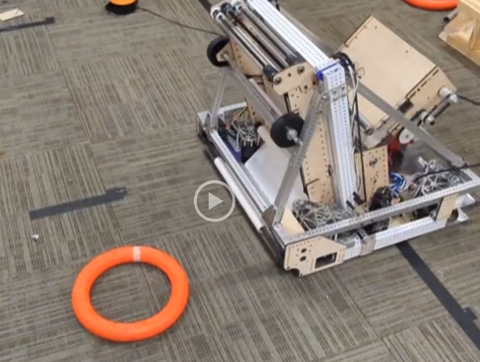
We did more testing on the Amp and Trap mechanism. Here are some videos of our progress. Here are Photos and videos of these in action. There are more on our Photo Album.

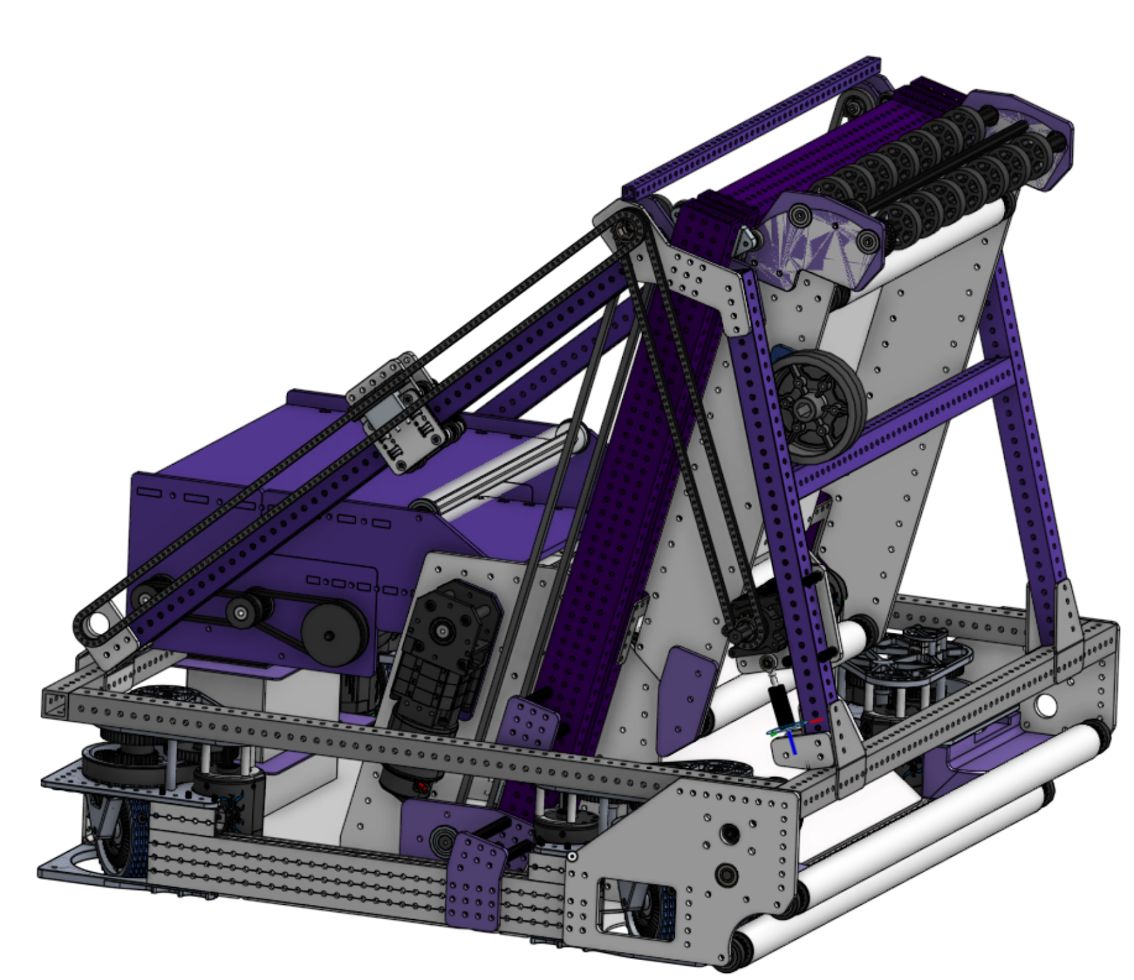
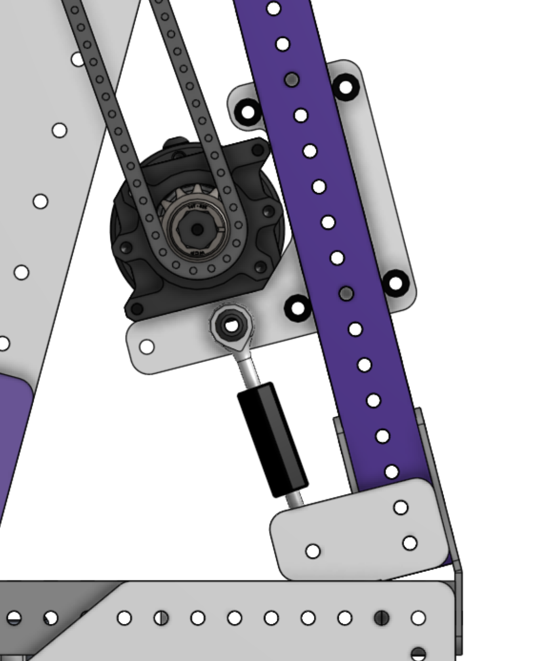
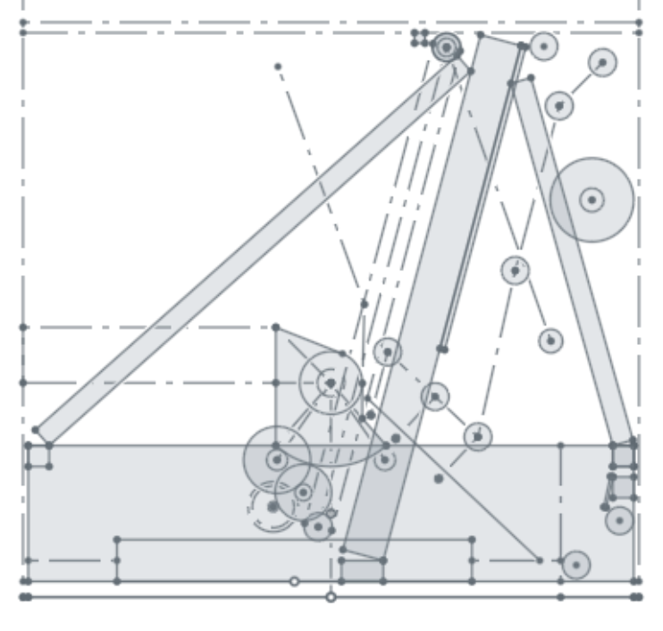
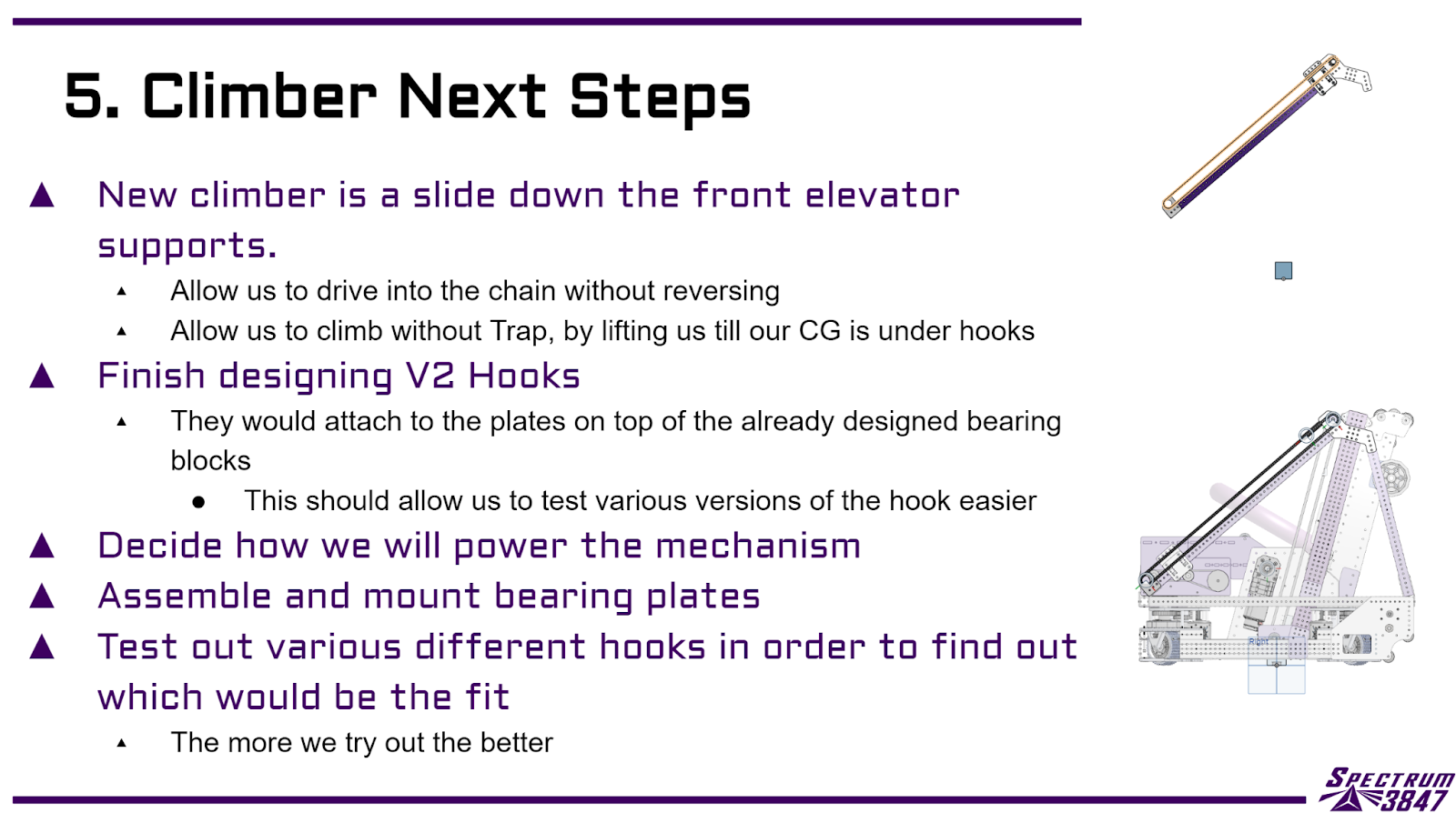
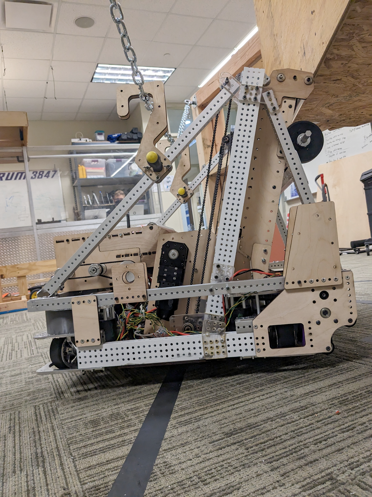
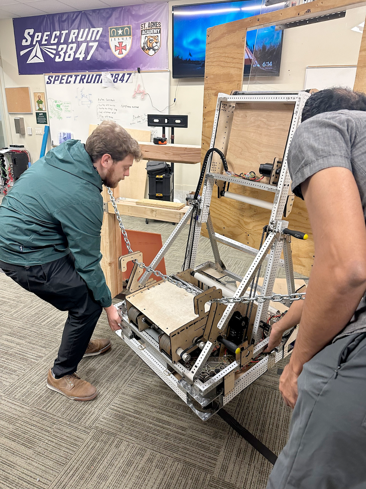
balanced climb test
We made a low-fidelity version of our new climber to test the balancing. We feel confident with this design to keep moving forward with a higher-fidelity version for alpha.
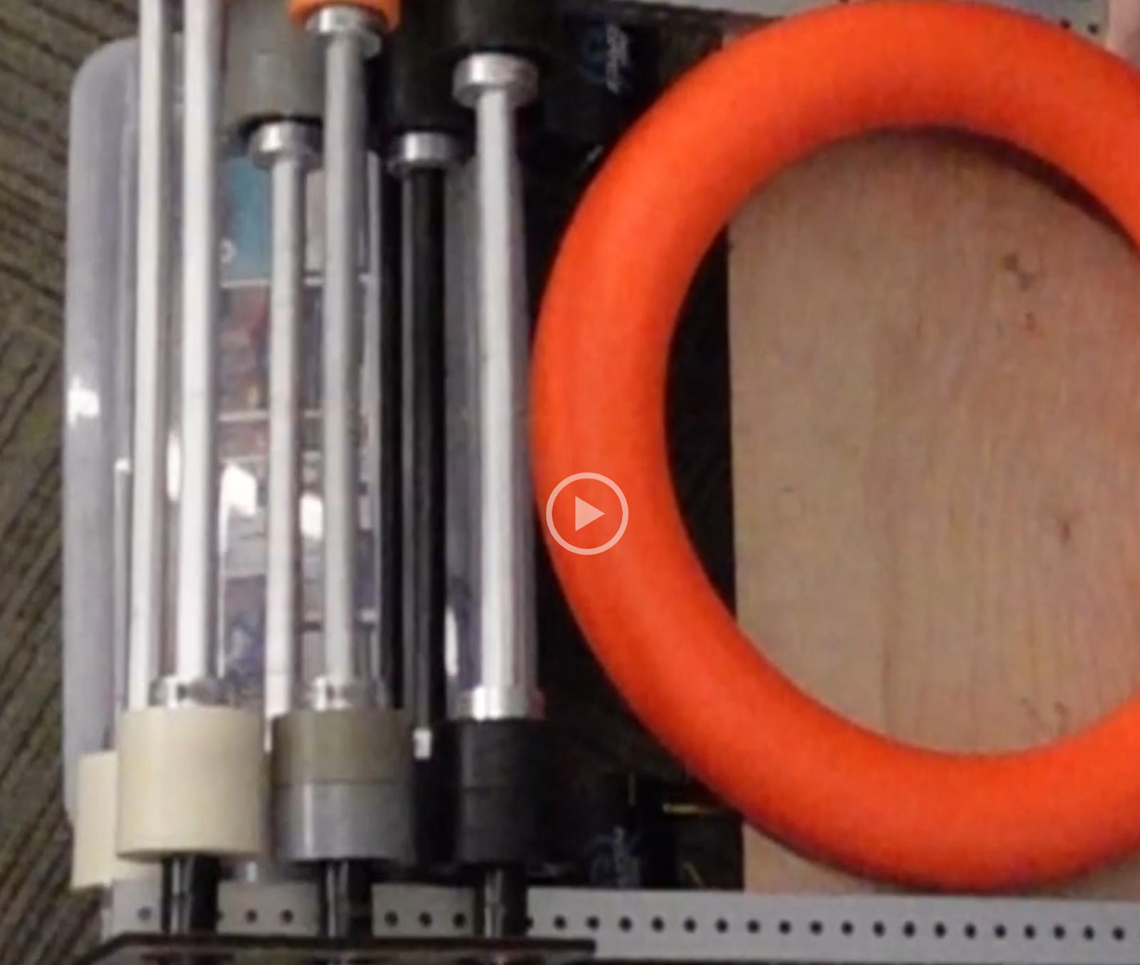
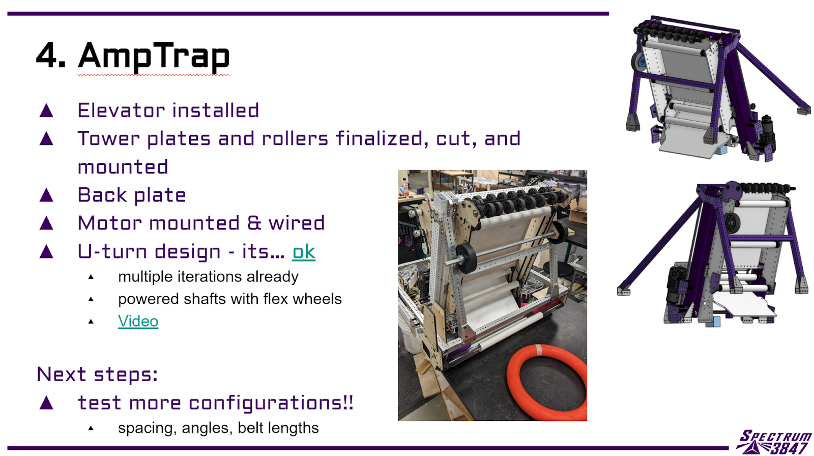
Trap Test
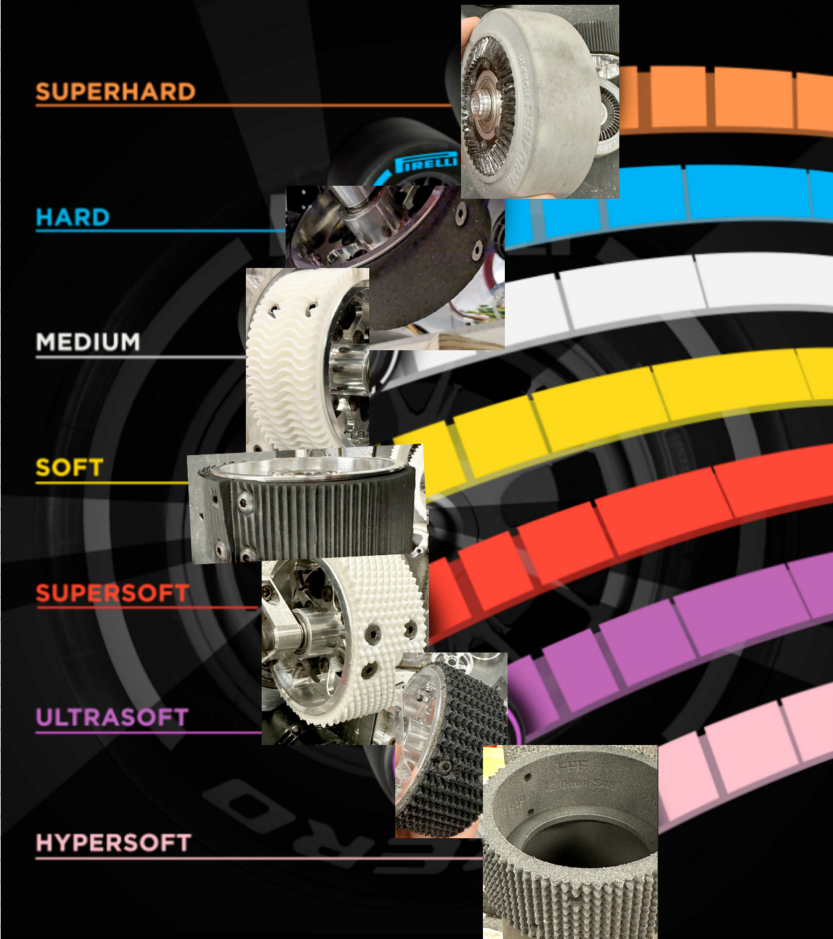
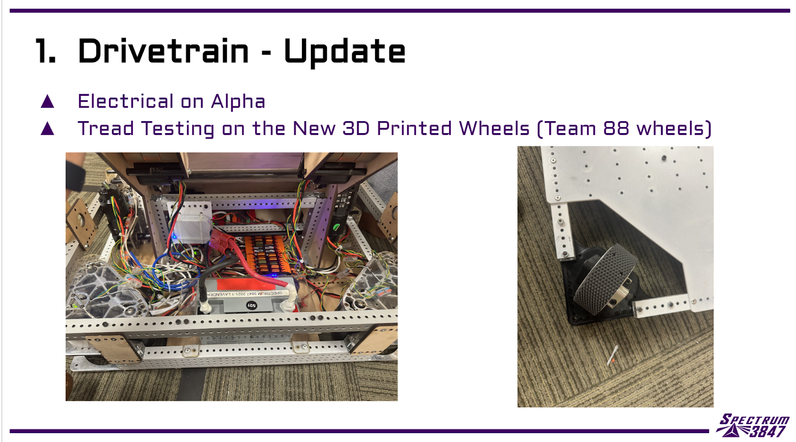
Team 88 SLS Wheels
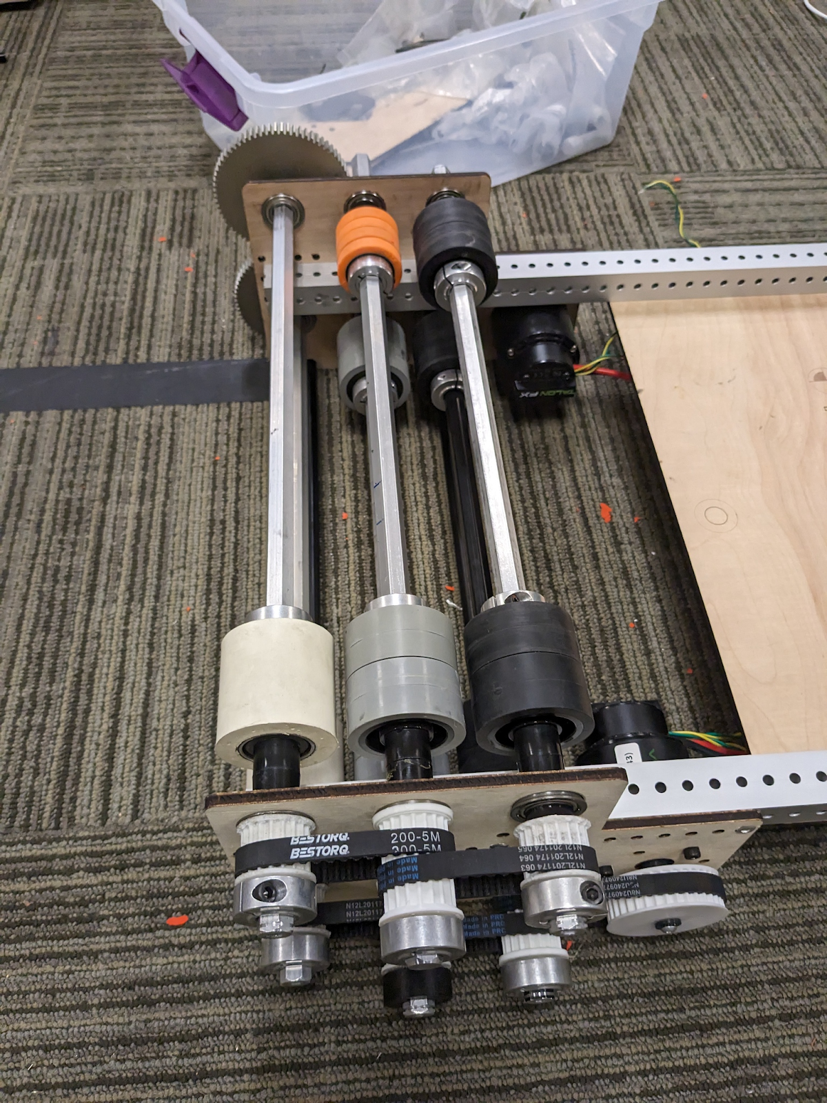
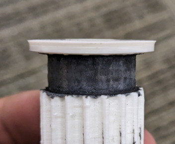
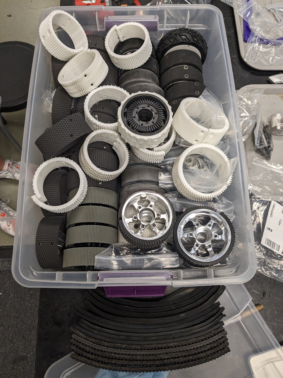
We recently tested SLS Printed Wheels from Team 88 on our traction jig, alongside our usual array of wheels. The goal was to see how these wheels were compared in terms of grip. We’d like to thank Team 88 and Formlabs for providing us these tires for us to test.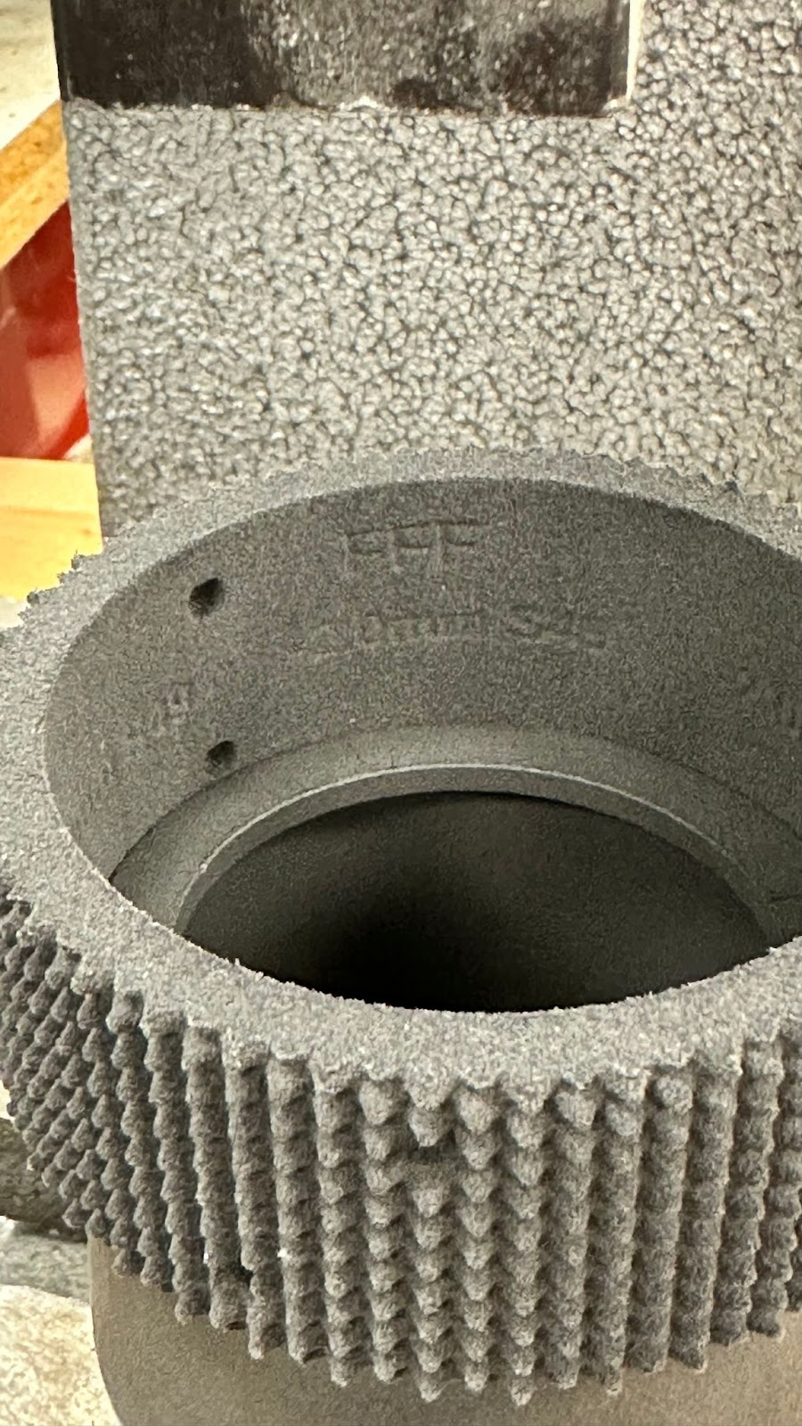
The data from our tests show that the SLS Printed Wheels provide superior traction. They outperformed other materials with the highest average angle and coefficient of friction (CoF) measurements. Here are our findings:
| SLS Printed Wheels | Black Nitrle | 3D Printed Spikes no Suspension | Treaded Neoprene | 3d Printed Waves (White) | Slick Neoprene | Colsons |
Test 1 | 68.5 | 56 | 47.8 | 56.5 | 48.5 | 45 | 42.5 |
Test 2 | 62.2 | 57 | 58 | 55 | 49 | 45 | 41.8 |
Test 3 | 65 | 57.2 | 60 | 57.3 | 47 | 42 | 42.8 |
Test 4 | 62.5 | 57.9 | 59 | 51 | 52 | 44.8 | 41.5 |
Test 5 | 64.8 | 57.1 | 55 | 55 | 52 | 45 | 41.2 |
avg Angle | 64.6 | 57.04 | 55.96 | 54.96 | 49.7 | 44.36 | 41.96 |
CoF | 2.106 | 1.542 | 1.480 | 1.426 | 1.179 | 0.978 | 0.899 |

While the SLS wheels lead in grip, we haven't yet assessed their durability. The next step is to test these wheels on our Alpha robot to monitor wear and tear.
Stay tuned as we continue to test and evaluate to determine the best wheel for our robotics applications.